In this post Brian from BD Loops explains how to properly Meg and Inductance Loop (http://www.bdloops.com)
How to Properly Meg an Inductance Loop
These easy to follow instructions will help you effectively test inductance loops.
Warning: I wanted to start this guide off with a friendly warning, while the megohmmeter is turned on you will want to make sure you never touch both metal leads from the megohmmeter at the same time, you will get shocked.
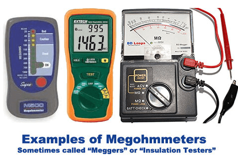
Step 1: Do you have a Megohmmeter or a Multimeter?
$133.00
BD Loops Megohmmeters are the only meter than can test for the most common loop issue - a nick in the insulation causing the loop to short to ground. This is why they are referred to as "Insulation Testers". This analog… Read MoreBD Loops Analog Megohmmeter Loop Tester

To properly “meg” a loop we must use a megohmmeter and not a multimeter. Because multimeters have an “ohm” setting many installers falsely believe that a multimeter can be used to “meg a loop”. Here is a quick look at how megohmmeters and multimeters differ:
Multimeters generally measure Continuity, Resistance, and Voltage. (For loops multimeters will check continuity, but will not tell you if the loop is shorting to ground.)
Megohmmeters are Insulation Testers. (Megohmmeters will tell you if the loop wire's insulation has been nicked as is causing a short to ground.)
Step 2: Okay I have a Megohmmeter, now what?
Fantastic! Here are step by step instructions on how to test a loop using a megohmmeter. What you really want to look out for here is making sure that you’re attaching one of the megohmmeter’s clip to an earth ground (such as an operator chassis) and the other clip to one of the loop’s lead-in wires.
Step 1: Remove the loop lead from the operator or detector.
Step 2: Attach one of the megohmmeter's clips (if your megohmmeter has clips) to an earth ground such as the operator frame or a 12" screwdriver driven into the ground. (You can pour water on the screwdriver to help ground the connection.)
Step 3: If the device has switches on it, make sure it is set to the MΩ position.
Step 4: Touch the other clip or lead from the megohmmeter to one of the loop lead-ins.
Step 5: Read the Meter.
If you are using an analog meter look at the needle's position:
Below 10 - Bad Loop (This Loop will need to be replaced)
10-20 - Suspect or Questionable Loop (we highly recommend that you replace the loop)
45-2000 - Good Loop
Step 6: Water down the area of the loop and lead-in and then take another reading. Loops often require water in the groove to facilitate a short to ground, and will read as a good loop in dry conditions. Is your reading significantly lower with water in the groove?
If you are using a digital meter: (They are a bit more difficult to read)
You will likely have to read the instructions that came with your meter to make sure you are interpreting the results correctly. Some digital meters give number readings similar to the analog meters, and in that case use the chart above. Some meters have lights that will tell you if the loop is good, questionable, or bad.
In Summary:
It is important to remember that only one of the megohmmeters clip leads will be connected to the loop, the other must be connected to ground.
We know that it is not very intuitive since you have 2 clip leads from the megohmeter and 2 lead-in wires on the loop, many installers will clip both leads to the loop. If an installer does connect both clip leads to the loop the megohmmeter will incorrectly show that the loop is bad or failing. (Go ahead and test it yourself, It won't damage the loop.)
We want to prevent installers from accidently replacing good loops by making such a small mistake while testing.
All credit to Brian Dickson and BD LOOPS